In this practical, we will create a unique cloud proximity detector using the Keyestudio Arduino Super Starter Kit, which integrates with AWS IoT services. The project will use a combination of sensors, actuators, and cloud services. By the end of this practical, you will understand the benefits of utilizing AWS for IoT networks and learn how to optimize costs, resiliency, and low latency in your deployments.
Assembling the circuit
First, we will assemble the hardware of the project:
Connect the NodeMCU ESP-32S, IR proximity sensor, piezo buzzer, and WS2812 RGB LED strip as shown here:
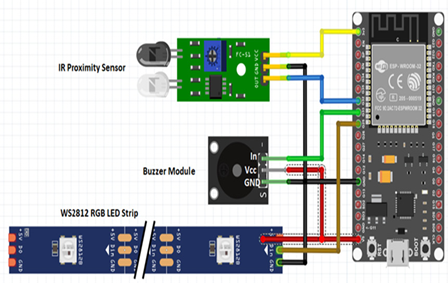
Figure 7.7 – Wire-up diagram of the hardware of the project
Connect the IR proximity sensor to the breadboard. Connect the VCC pin to the 3.3V output on the NodeMCU, the GND pin to GND, and the data pin to GPIO 36 (also known as VP or ADC1_CH0) on the NodeMCU.
Connect the RGB LED strip to the breadboard. Connect the VCC pin to the 3.3V output on the NodeMCU using a 220-ohm resistor to limit the current flow. Connect the GND pin directly to the GND and the data pin to GPIO 5 on the NodeMCU.
Connect the piezo buzzer to the breadboard. Connect the positive pin to GPIO 4 on the NodeMCU through a 220-ohm resistor. Connect the negative pin directly to GND on the NodeMCU.
Writing the code
Upload the following code to your Arduino board, replacing <YOUR_WIFI_SSID> and <YOUR_WIFI_PASSWORD> with appropriate values. We use a similar sketch as the previous one to publish data to AWS. We add the FastLED library to control the WS2812 LED strip and use ESP32 ADC1 (analog-to-digital converter) to control the buzzer and read the IR proximity sensor. Please note that ADC2 is used by ESP32 to accommodate Wi-Fi functions, so we cannot use it:
We create a loop function that continuously checks the AWS client’s connection and reconnects if needed. It then reads the value from the IR sensor to detect obstacles. If an obstacle is detected (when the sensor value is below 500), it prints a message, plays a tone on a buzzer, and animates the LEDs. Otherwise, the LEDs are reset. Additionally, the program publishes a message every 10 seconds, and then it waits for a second before restarting the loop:
Finally, we declare some miscellaneous functions that allow us to play a tone, animate the LEDs, and reset the LEDs as per the loop.
After copying the previous sketch, we need to create a new tab in the Arduino IDE by clicking on the … sign near the top-right window:
Choose Create new tab and give the new tab a name, such as secrets.h.
Paste the code in the following code block into the new tab that we have created and insert the AWS root CA certificate, device certificate, and device private key that we got in the A practical exercise utilizing the services section. Insert the certificates between the lines BEGIN CERTIFICATE and END CERTICATE for those three certificates. Change WIFI_SSID and PASSWORD according to your Wi-Fi credentials. Also, replace AWS_IOT_ENDPOINT with your own endpoint:
#include <pgmspace.h>
#define SECRET
#define THINGNAME “ESP32Thing”
const char WIFI_SSID[] = “YOUR_WIFI_SSID”;
const char WIFI_PASSWORD[] = “YOUR_WIFI_PASSWORD”;
const char AWS_IOT_ENDPOINT[] = “AWS_IOT_ENDPOINT”;
// Amazon Root CA 1
static const char AWS_CERT_CA[] PROGMEM = R”EOF(
—–BEGIN CERTIFICATE—–
—–END CERTIFICATE—–
)EOF”;
// Device Certificate
static const char AWS_CERT_CRT[] PROGMEM = R”KEY(
—–BEGIN CERTIFICATE—–
—–END CERTIFICATE—–
)KEY”;
// Device Private Key
static const char AWS_CERT_PRIVATE[] PROGMEM = R”KEY(
—–BEGIN RSA PRIVATE KEY—–
—–END RSA PRIVATE KEY—–)KEY”;
Now that we have initialized our necessary hardware and cloud modules on AWS, we are ready to test the installation.
Leave a Reply